All Products · F-Series

F-Series · Fiberglass

GR90 Sliding Window

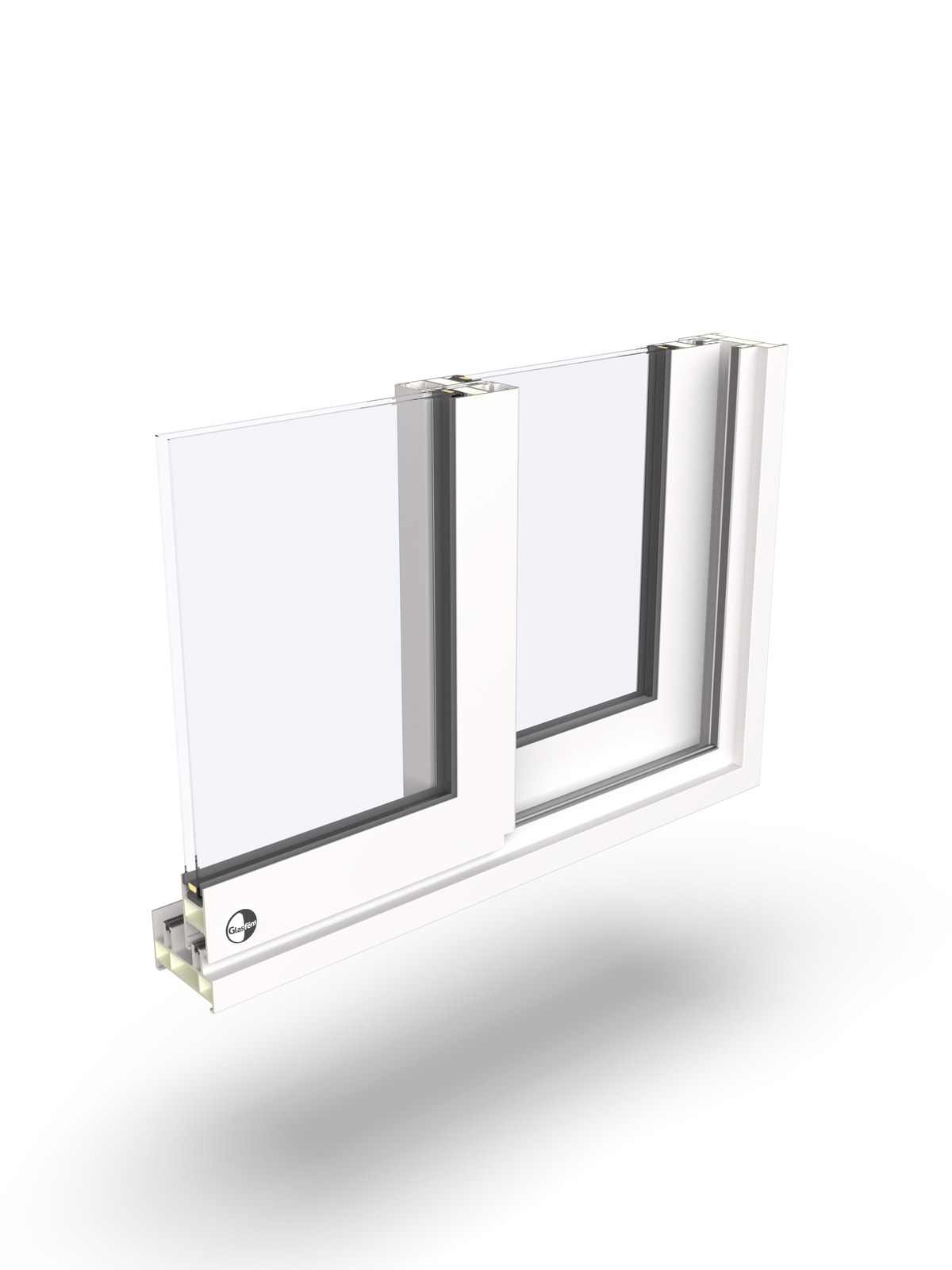
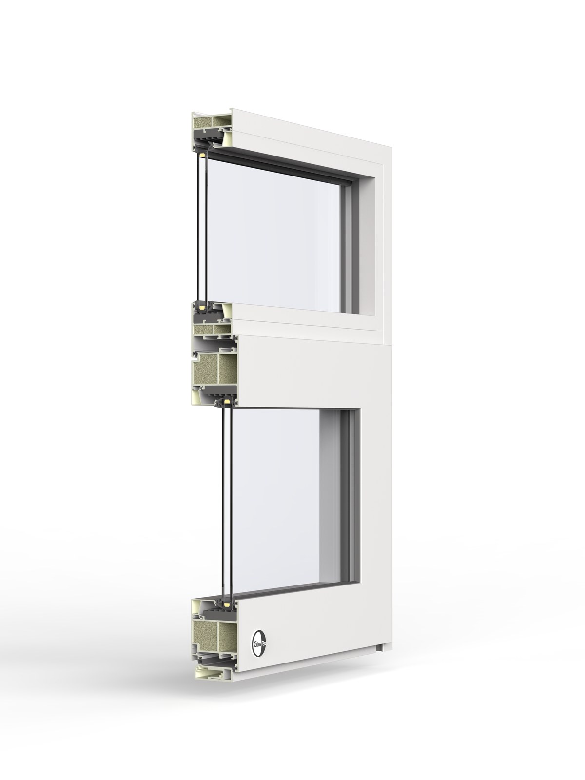
A 90 mm horizontal sliding window in pultruded fiberglass — one sash glides past the other for ventilation without projecting into a walkway or balcony.

Frame
Pultruded fiberglass · 90 mm
Opening
Sliding
Glass package
Double or triple · up to 40 mm
Whole-window U-value
0.19 Calculated
Certified: third-party tested (NFRC, CSA) Calculated: LBNL THERM / WINDOW Project-specific: by size and glass

The slider keeps both sashes in plane, so nothing swings out over a walkway — useful on tight balconies and pass-throughs. The 90 mm fiberglass frame carries the glass weight while keeping the meeting rail slim.

Technical specifications
Frame depth90 mm
Frame materialPultruded fiberglass, powder-coated
Glazing pocketUp to 40 mm
OpeningHorizontal sliding
Whole-window U-value0.19 W/m²K  Calculated
SHGC0.20–0.50 by glass  Project-specific

Certified values are published as NFRC and CSA testing completes. Calculated values come from LBNL THERM and WINDOW models of the specific assembly. Project-specific values depend on size and glass package.

What is a sliding window or door?

A sliding window or door runs one or more panels horizontally on a track, one gliding past the next. Because the panels stay in the plane of the wall, a slider opens a wide view and passage without sweeping into the room, which is ideal where floor space is tight. Configurations run from two panels up to multi-panel and pocketing runs that slide away into the wall.
See all window & door types ›

Glass & glazing options
Double or triple · up to 40 mm. Low-E and solar-control coatings, warm-edge spacers, argon or krypton fill, laminated and acoustic packages to suit the project.
Hardware
German tilt-turn hardware with concealed hinges and multi-point locking. Handle finishes in nine anodized and powder-coated options — see Finishes.
Sizes & configurations
Single and coupled multi-lite arrangements. Maximum sizes are governed by the weight of the glass package and, for the A-Series, the design wind load; see drawings for limits.
Drawings & details
Head, jamb, and sill sections, anchoring and interface details, and DXF profiles available on request while the drawing library is finalized.
Installation
Rough-opening tolerances, substrate requirements, and air-barrier interface guidance follow the F-Series installation manual. See Air Barrier Interface and Installation.
Downloads & resources
Spec sheet, NFRC label (on certification), and BIM objects will be posted here. Ask us for the current data package for your project.